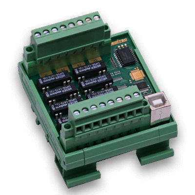
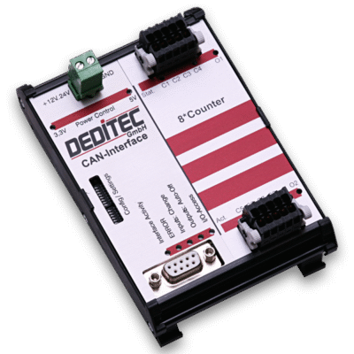
Configuration of CANopen modules
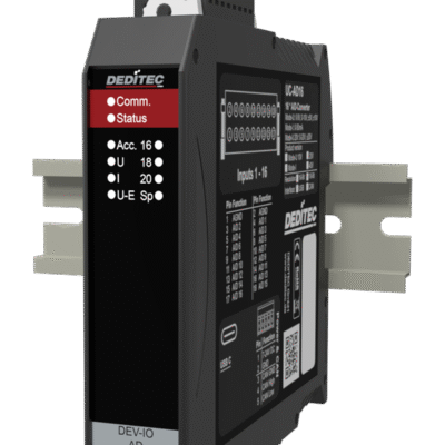
The CANopen interface is configured via the CANopen bus of the module and via three rotary coding switches located on the front of the module.
The upper and middle rotary coding switches determine the node ID, the lower one the baud rate.
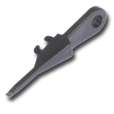
Rotary coding switch
The upper rotary coding switch determines the high-order bits and the middle switch the low-order bits.
The lower rotary coding switch is used to set the baud rate, the following is a list of all settings:

Meaning of lower rotary switch:
| Value | Operating mode | Description |
| 0 | CANopen | Bitrate = 1000 kBit/s |
| 1 | CANopen | Bitrate = 800 kBit/s |
| 2 | CANopen | Bitrate = 500 kBit/s |
| 3 | CANopen | Bitrate = 250 kBit/s |
| 4 | CANopen | Bitrate = 125 kBit/s |
| 5 | CANopen | Bitrate = 100 kBit/s |
| 6 | CANopen | Bitrate = 50 kBit/s |
| 7 | CANopen | Bitrate = 20 kBit/s |
| 8 | CANopen | Bitrate = 10 kBit/s |
| 9 | CANopen | Autobaud + LSS |
| A | CANopen | Autobaud |
| B | CANopen Bootloader | Bitrate = 250 kBit/s |
| C | CANopen Bootloader | Bitrate = 1000 kBit/s, Node ID = 0x7e |
| D | CAN 2.0 A/B | Use settings from EEPROM |
| E | CAN 2.0 A/B | Bitrate = 1000 kBit/s, CAN ID = 0x100 |
| F | CANopen | Bitrate = 1000 kBit/s, CAN ID = 0x7e |
Control of CANopen modules
EDS
Select the EDS file for your module to load all the registers required for the controller.

Read register
Under the "Device Profile Segment" tab, you will find all the registers for controlling the module.
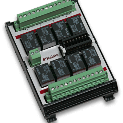
In register 0x6200 it is possible to write or read the states of the relays.
In the example, the status of the first 8 relays is read.

Write register
Under the "Device Profile Segment" tab, you will find all the registers for controlling the module.
In register 0x6200 it is possible to write or read the states of the relays.
In the example, the status of the first 8 relays is written.