

Control of our CAN modules
Our CAN modules enable the automatic exchange of I/O data as well as targeted access to individual module functions. Two operating modes are available for this purpose:
1. Auto TX/RX mode: Automatically transmit and process CAN messages via RAW CAN or using J1939 addressing – without requiring an additional control PC during operation.
2. DELIB command mode: Read and write module registers selectively via the open DEDITEC communication protocol.
The available I/O functions depend on the configuration of the module used.

1. Auto TX/RX mode for RAW CAN and J1939
In Auto TX/RX mode, the module independently transmits and processes CAN messages. This makes it possible, for example, to transmit measured values, switch digital outputs, or set analog output values.
Configuration is carried out using the free ICT-Tool and does not require any custom programming. In addition to predefined data assignments, Message Composers are available for individually configured transmit and receive messages.
RAW CAN: define the CAN ID directly
With RAW CAN, you can choose between an 11-bit CAN ID and a 29-bit CAN ID. You then enter the required CAN ID directly.
Independently of this, the I/O mode determines which module values are transmitted or how received payload data is processed. The CAN ID therefore defines the message address, while the I/O mode defines the data processing.
J1939: configure message addressing clearly
SAE J1939 is a CAN-based communication protocol used, among other applications, in commercial vehicles, agricultural machinery, construction machinery, and industrial systems.
In J1939 mode, the message address is entered using separate fields:
- Prio: Priority of the message on the CAN bus.
- PGN: Identifies the parameter group or type of message.
- SA: Address of the transmitting CAN node.
- DA: Address of the intended recipient, provided that the PGN used supports destination addressing.
The ICT-Tool automatically generates the corresponding 29-bit CAN ID from these values. When reading an existing configuration, the stored ID is split back into its individual components.
J1939 mode therefore simplifies the entry and display of the message address. Which payload data is transmitted and how it is processed is defined independently via the I/O mode or the Message Composer.
Automatic transmission: TX mode
In Auto TX mode, the module automatically transmits CAN messages to other nodes. Depending on the module configuration, this can include digital input states, stored flip-flop states, counter values, or analog input values.
Messages are transmitted at a defined time interval, when a specified event occurs, or – depending on the selected trigger mode – as fast as possible.
In the ICT-Tool, configure the following settings:
- Enable the respective TX mode.
- Configure CAN addressing via RAW CAN or J1939.
- Select the I/O data to be transmitted or the required Composer configuration.
- Define the transmission trigger and, for time-controlled transmission, the transmission interval.
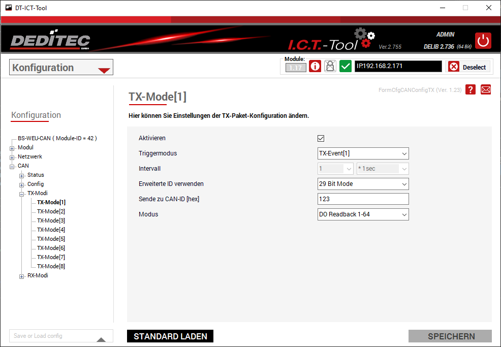
Predefined modes are available for frequently used data configurations. Individual messages can be created using the TX Message-Composer.
TX Message Composer: configure transmit data individually
The TX Message Composer allows you to combine different module values and fixed data values within a CAN message. Four independent Composer configurations are available, each permanently assigned to one of the first four corresponding TX modes.
For each entry, you select the data source and the associated channel or channel group. Digital inputs, for example, can be transmitted individually or in groups. Fixed hexadecimal values from 0x00 to 0xFF can also be inserted, with each value occupying one data byte.
Data format and byte order
Depending on the function and the remaining space, data lengths of 1, 2, 3, or 4 bytes as well as 4-byte floating-point values (Float) are available. For multi-byte integer values, you can select the byte order:
- LSB: The least significant byte is transmitted first.
- MSB: The most significant byte is transmitted first.

The entries automatically occupy the data bytes sequentially in the configured order. The “CAN data bytes x/8” display shows the amount of space used within the maximum eight data bytes of a classic CAN message.
Scale values before transmission
If required, scaling can be enabled for an entry:
New value = (Old value + Offset) × Multiplier
This allows you, for example, to convert an analog raw value into a voltage value before transmission and transmit it as a floating-point value.
Automatic reception: RX mode
In Auto RX mode, the module automatically evaluates incoming CAN messages and applies the contained values to its functions or outputs. This makes it possible, for example, to switch digital outputs and relays or set analog output values.
In the ICT-Tool, select the message address to be evaluated via RAW CAN or J1939. Then use the I/O mode to define how the received payload data is processed.
Four RX Message Composer configurations are available for custom data assignments. The data is processed directly by the module; no additional PC application is required during operation.
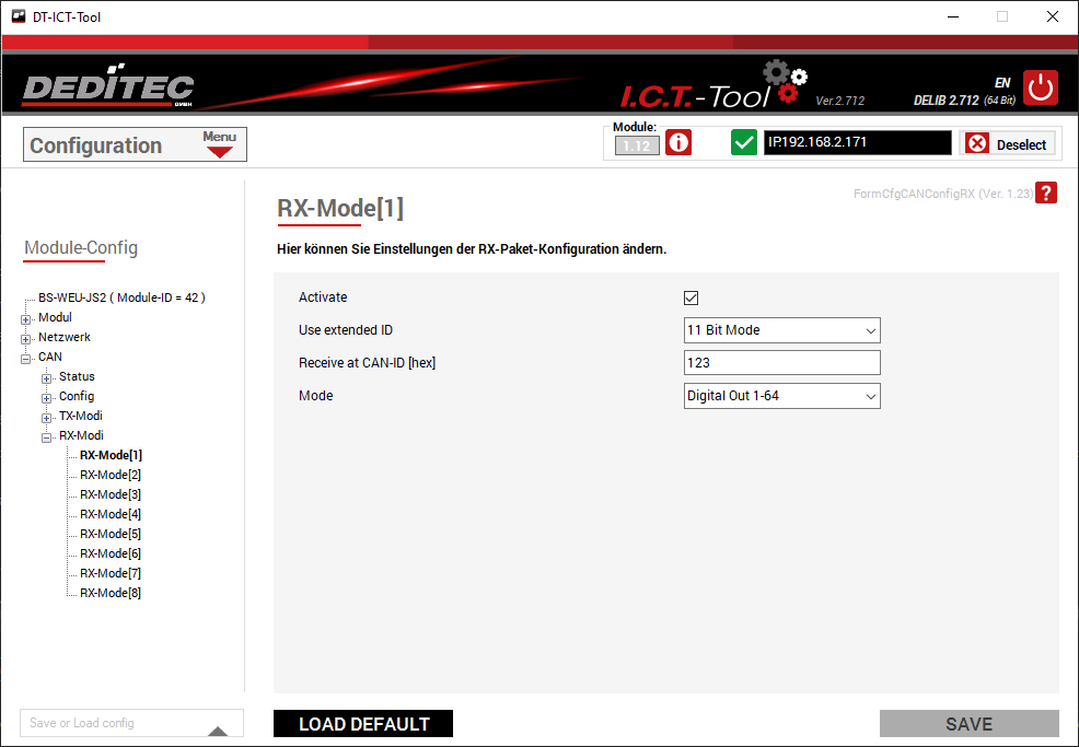
RX Message-Composer: process received data selectively
The RX Message-Composer allows you to define how the data of a received CAN message is split, evaluated, and assigned to the module functions. The four independent configurations are permanently assigned to the first four corresponding RX modes.
For each entry, you define the data length, data format, target, and output channel or channel group. The data bytes are automatically assigned sequentially according to the order of the entries. Depending on the function and the available space, data lengths of 1, 2, 3, or 4 bytes as well as 4-byte floating-point values are supported. For multi-byte integer values, either LSB or MSB byte order can be selected.

Control digital and analog outputs
Depending on the module configuration, received values can be assigned to an individual digital output, a group of digital outputs, or an analog output.
Two number encodings are available for analog outputs:
- D/A OffBin: Uses the received 16-bit value in the Offset Binary encoding required for the D/A output.
- D/A Signed: Interprets the received 16-bit value as a signed Two’s Complement value and automatically converts it to Offset Binary before output.
The number encoding and byte order are independent settings.
Skip unused data
Use “Ignore” to skip data ranges that are not relevant to the module. This preserves the correct assignment of subsequent values within the message.
Scale values and evaluate conditions
Received values can also be adjusted using an offset and multiplier before further processing:
New value = (Old value + Offset) × Multiplier
Depending on the selected target, various operations are also available. In addition to direct assignment and inversion of digital states, comparisons and range checks can be used for individual digital outputs.
For example, an output can be switched on when a received value exceeds a limit value or lies within a defined value range. Simple comparisons use “Value 1”, while range checks additionally use “Value 2”.
DELIB command mode
DELIB command mode enables targeted access to the module registers via the open DEDITEC CAN protocol.
The protocol can be implemented on devices with a suitable CAN interface without using the DELIB driver library. Communication is therefore independent of the operating system used.
The structure of the CAN messages and the required register addresses are documented in the “Protocols & Register Assignment” manual. It contains the information required to implement custom read and write access.
Further information is available in our CAN protocol documentation in the download section.