Installation and test - ICT tool
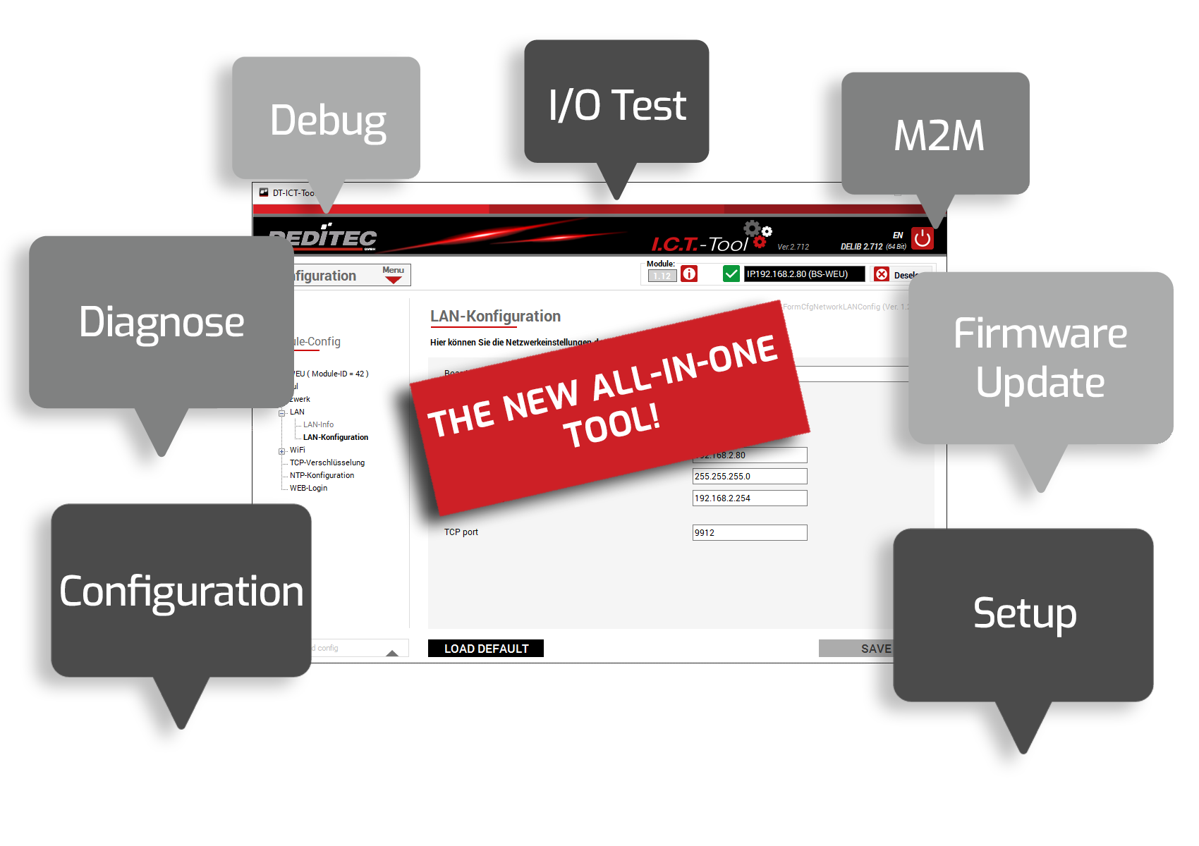
We provide you with our all-in-one ICT-Tool for commissioning and testing our modules.
The ICT-Tool
Integration, configuration and testing - Our all-in-one Windows tool contains all the functions you need to put our products into operation quickly, easily and efficiently. Start with the setup and configuration, install firmware updates and use the extensive test and diagnostic options. The integrated help menu provides additional support if required.
Entry
Below you will find a brief overview of the program's basic menus.
Module selection
Here you can integrate a new product into the ICT tool by clicking on the "+" symbol and then configure it.
Module information
Here you will find a brief overview of the selected module. The manual is also available as a PDF or HTML version.
All available module IDs can also be called up. This ID is required to integrate our products into your software projects.
ICT TreeView
In the TreeView, on the left-hand side of the program window, you can see the respective control elements or functions that are supported by your selected module. The scope of the functions depends on the respective product.
The "Configuration" menu
Info
All relevant module information can be called up here at a glance.
- Module name
- Module ID
- Firmware revision
- Interface type
- Current DIP switch setting (only for Ethernet modules)
Identification
If several DEDITEC Ethernet modules are active in the network, a signal LED on the selected module can be activated via an identification function. This facilitates visual assignment.
Restart
You can restart your module here. The module status shows whether the restart was successful.
USB configuration
If you want to use several USB modules from the same product series on one PC, each of these modules must first be assigned its own module number.
LAN info
On this information page, you will find the current LAN network information and all the settings for your module at a glance.
LAN configuration
Integrate the product into your network or control it directly via a 1-to-1 connection.
The following parameters can be changed.
- Board name
- DHCP on/off
- IP address
- Subnet mask
- Default gateway
- TCP Port
WiFi info
All important WiFi settings are displayed on this page
WiFi configuration
Here you can change the network settings of the selected WiFi product.
The following settings can be made:
- Board name
- WLAN on/off
- Router name
- Router password
WPS
With the WPS function, your module can be connected to the router quickly and easily, automatically (WPS on the router is required)
CAN configuration
With our CAN products in the BS, NET and UC series, settings for the interface and the TX/RX packets can be made using the ICT tool.
More information can be found here:
Serial configuration
For our serial products in the BS, NET, UC and RO series, changes to the interface can be made using the
ICT tool.
More information can be found here:
TCP encryption
Here you can make settings for the encryption of your module.
The following configurations can be made.
- Allow unencrypted protocol
- Allow "User" encryption mode
- User password
- Allow "Admin" encryption mode
- Admin password
NTP configuration
You can make changes to the NTP service here.
The following configurations can be made.
- NTP service on/off
- server
- Port
- Timezone
WEB-Login
Here you can change the login settings of the web interface.
The following configurations can be made.
- Session duration
- Login name
- Login password
- Allow I/O access via web interface
D/A Default Values
Here you can set the D/A values and modes with which the module should be started.
The value and mode can be set individually for each channel.
Watchdog configuration
Here you can make and save settings on your watchdog stick.
Save or Load config
Using the "Save or Load config" function, you can save your entire module configuration in an external XML file.
This means you can always load your module in the desired original state.
The following configurations can be saved depending on the module type.
- USB configuration
- LAN configuration
- WiFi configuration
- TCP encryption
- NTP configuration
- Serial configuration
- CAN configuration
The "M2M" menu
Status
This gives you an overview of the activity of the transmitter and receiver module
The following information from the transmitter module is displayed:
- Status of the activity: If the check mark is set, this action is currently being performed.
- Total number of actions performed. Is reset to 0 after a restart of the module.
- Number of actions per second.
- Number of DELIB errors that occur when executing commands from the DEDITEC driver library.
The following information from the receiver module is displayed:
- Connected: If the check mark is set, the transmitter and receiver modules are connected.
- IP address of the receiver module.
- Number of connection attempts.
Receiver modules
You can set the network settings of the receiver module here.
The following settings can be made
- Name for the receiver module
- Network settings of the receiver module
- Timeout
- Encryption type/ password
Action
With an action, you define which input signal is to be sent from the transmitter module to which output of a receiver module.
The following settings can be made:
- Type of task (digital, analog)
- Which receiver module should be used
- The interval at which the operations are to be carried out
- Start channel of the transmitter module
- Number of channels to be transmitted
- Start channel of the receive module
In the image on the right, DI data is sent every 100ms from channel 3(CH Start) to channel 8 ((CH Start) + (CH Count)) to channels 0-5 of the target module.
The "Event Control" menu
Status
The Status area provides an overview of all active events and executed actions.
The following information is listed:
- Event number
- Event type
- Time interval of the event
- Number of events that have occurred
- Action number
- Number of triggered actions
- Number of other actions
Events configuration
Up to 16 different events can be created in the configuration menu. An event can be used, for example, to define switching thresholds at the analog inputs or logical states at the digital inputs of the module and link them to an executable action. The configuration itself is saved permanently in the module configuration memory of the module.
The following event modes are available, depending on the module type:
- DI: High-Low state of a digital input.
- DI flip-flop: Status change of a digital input (is stored in the module with the so-called flip-flop flag and deleted again after readout).
- DO readback: ON-OFF status of a digital output (is read out using a DO readback command).
- A/D: Current or voltage level at the analog inputs
Configuration actions
Up to 16 different actions can be created in the configuration menu. An action defines what should happen within an event after a condition is met.
The following action modes are available, depending on the module type:
- Set DO output: Switches a digital output on or off
- Set D/A output: Outputs a current or voltage value at an analog output
- Send CAN packet: A special CAN TX event is triggered (up to eight CAN TX events can be configured separately).
The "I/O Tests" menu
Digital Out
All digital outputs of your product can be checked by clicking on the buttons.
The following switching options are possible:
- Switching on and off channel by channel
- Channel-by-channel switching on or off for a specific time (product-dependent)
- Reading back the switching status (readback)
Digital In
In this view, the logical states of all optocoupler inputs can be read out.
The following information is displayed:
- Logical status of the inputs (ON/OFF)
- Number of detected pulses (counter function)
- Change of state detected (flip-flop)
TTL I/O
In this menu, the TTL channels of the module can be configured as inputs or outputs. The individual TTL outputs can be switched on or off by pressing the buttons. In addition, the status of all TTL inputs can be read out.
The tool offers the following functions:
- Configuration of the channels as input or output (in blocks of 8)
- Switching on and off channel by channel
- Reading back the switching status (output readback)
- Displaying the logical status of the inputs (input readback)
Analog Out
Here you can test the analog outputs of the module and manually enter any voltage or current value.
Analog In
In this menu, voltage or current values of all A/D channels can be displayed.
It is also possible to activate our A/D software filter with different filter levels.
CAN Runtime Parameter
Here you can change the CAN settings of the interface, the RX and TX packets in runtime.
The following settings can be made:
- Baud rate
- Extended ID
- Active on/off
- CAN ID
- Mode
CNT48
Here you can read out the counter readings of a counter module, select filter options and set various counting modes.
The following counting modes are supported:
- Read on rising edge
- Read on rising edge x2
- Read on rising edge x4
- Period duration
- Frequency measurement
- PWM measurement
Pulse generator
The pulse generator can be used to generate square-wave signals. High and low time as well as the number of pulses can be set here.
PWM Out
In this menu you have the option of testing various PWM frequencies. In addition, the duty cycle can be entered manually for each individual channel.
Temp
The temperature of all connected temperature sensors is displayed here directly in °C.
Graphical display
This menu allows a graphical representation of all analog input signals, such as A/D, temperature or FIFO-IN.
Watchdog
This tool can be used to check the configured watchdog parameters for correct function.
I/O – Timeout
You can use the timeout function in the I/O area to simulate a timeout case for your module.
The following is a description of the timeout window
- Read / Write symbol: Flashes to indicate an active connection to the module
- Automatic access: Removing the tick triggers a timeout after the timeout time has expired
- Manual access: Manual retrieval of data from the module
- Timeout status: Shows whether the timeout is active and whether a timeout event has occurred
- Timeout mode: Selection between 3 timeout modes, Normal, Reactivate and Secure
- Timeout duration: The time after which the timeout should be triggered is set here
- Activate / deactivate: Activates or deactivates the timeout function
The "Diagnostics" menu
Access times tests
This test can be used to determine the access times to the module. The test values are read and written in 8, 16, 32, or 64-bit commands.
Access times Register
The following example checks the register accesses to an Ethernet module. The average access time here is 0.5 ms.
Access times Analog I/O
In the following example, the access times to an Ethernet module with analog I/Os are checked. The average access time here is 0.6 ms.
Access times Digital I/O
In the following example, the access times to an Ethernet module with digital I/Os are checked. The average access time here is 0.6 ms.
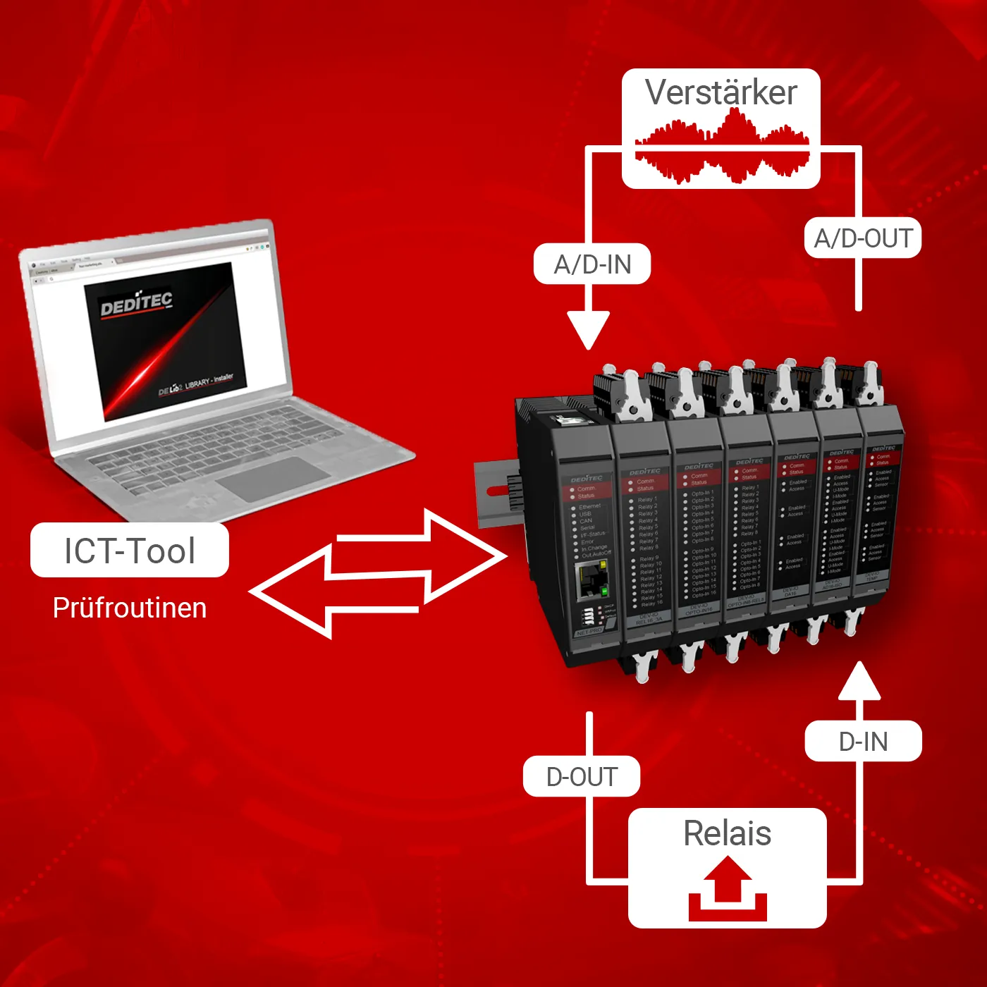
Cable return test
The cable return test can be used to check the function of all digital and analog inputs and outputs (I/Os) of a module. To do this, inputs and outputs are wired together externally on a 1:1 basis. The test software analyzes whether the output signals arrive correctly at the inputs, thereby identifying wiring errors or hardware defects.
Analog test
In analog test mode, the D/A converter outputs defined test voltages, which are then read in by the A/D converter and compared with the target values. The software counts the number of test runs and automatically documents any deviations.
Digital test
In the digital test, the switching states of the relay or MOSFET outputs are fed back externally to the optocoupler inputs. Here, too, the software counts and compares the number of cycles and automatically detects transmission errors or deviations.
A/D quality measurements
The quality of an A/D measurement is influenced by various factors and can be affected by external interference. A reliable method for checking measurement quality is to measure a stable battery voltage. Our diagnostic tools can be used to determine the residual ripple and noise behavior.
A/D ripple
The A/D ripple test can be used to measure the residual ripple of the individual A/D inputs and check for interference signals such as mains hum or voltage instabilities.
A/D noise
The noise behavior of each A/D channel can be displayed graphically using A/D noise measurement. Additional filter stages with averaging can be used to smooth and improve the measurement signal.
FIFO In/Out
Hier können Sie den Software-FIFO Ihres NET-Moduls testen und sich Statuswerte ausgeben lassen.
D/A output test
The D/A output test enables targeted testing of each individual D/A channel of a module. A freely selectable test voltage can be output directly. Currently, simple square wave signals with configurable high and low times are available. The signals can be monitored simultaneously with an oscilloscope. This function is also ideal for long-term tests. The test software detects DELIB errors and logs them automatically.
The "Firmware update" menu
To benefit from the latest functions and prevent errors, we recommend that you always keep your DEDITEC product up to date.
Flash Files
Downloading the firmware flash file package via the ICT tool
- Go to Flash Files in the "Firmware update" menu
- Click on the download button to start the download.
- Administration rights are required for the automatic unpacking of the flash files. If these rights are not available, the files are downloaded to the download area of your PC and must be extracted manually to the installation directory.
\DEDITEC\DELIB\programs\flash_files
Downloading the firmware flash file package via the DEDITEC homepage
- Download the required firmware flash file package from our homepage: Downloads -> Software -> Firmware
- Extract the files to the following installation path: ..\DEDITEC\DELIB\programs\flash_files
Flash modules
In the "Firmware update" menu, select the module you want to update and then click on the "Flash modules" or "Flash submodules" button.
The firmware is now updated and the module is then restarted automatically.
Information on the firmware flasher
The following information is displayed in the firmware flasher:
- Last FW: Displays the last firmware version
- Current FW: Displays the currently installed firmware version
- Newest FW: Displays the latest firmware version
- Log: Displays status or error messages during the flash process
The "Settings" menu
General
Here you can make general configurations to the ICT tool.
The following changes can be made:
- Language - setting between German and English possible
Updates
Here you can search for available DELIB or firmware updates.
- Automatic update search at program start
- Search for DELIB updates
- Search for firmware updates
Error log
Here you can make settings for the deditec_debug.log. This is saved under the path C:\Users\?USER?\AppData\Local\DEDITEC.
The following settings can be made:
- Enable writing to the debug.log
- Activate log notifications
- Activate automatic deletion of the debug.log
- Setting after how many days the debug.log should be deleted
- Set the maximum size of the debug.log
DELIB – DebugView – Global
Settings can be made here for the information that is to be displayed with the DebugView.
- Activate debug output
- Activate display of errors
DELIB – DebugView – Details
More detailed settings can be made here for the information to be displayed with the DebugView.
