Highlights
- CAN interface controlled input module
- 8 input counters (48-bit counters, max. 20 MHz frequency)
- 2 output counters (32-bit counters, max. 5 MHz frequency)
- 4 different input counter modes:
Pulse counting + pulse counting with reset / distance measurement / event counting / PWM measurement - LED status indication for each input
- Galvanic isolation of all inputs and outputs
CAN Counter Module for Capturing and Outputting PWM Signals
The company DEDITEC from Brühl introduces its new counter module RO-CAN-CNT8. This module features 8 input counters (48-bit) and 2 output counters (32-bit).
Among the many highlights of this module are the extremely precise PWM resolution (0.01% at 2 kHz, 0.1% at 20 kHz, and 1% at 200 kHz) and the 48-bit counter for each input channel.
The RO-CAN-CNT8 is equipped with 4 different counting modes, which can be configured independently for each of the 8 input channels. This gives users the flexibility to perform pulse counting, distance measurement, event counting, and PWM signal measurement.
The 8 input channels are factory-set for a switching voltage of 15V to 30V (reconfigurable to 5V – 12V) and are each equipped with a 48-bit counter. Each input channel also supports individual counter mode configuration and filtering. The maximum input frequency is 20 MHz.
The module’s 2 outputs (32-bit counters) support a maximum output voltage of 5V and a maximum output frequency of 5 MHz. The pulse quantity and low/high times (adjustable in 10 ns steps) can be preconfigured. PWM signals can also be output at 1 kHz, 10 kHz, or 100 kHz with very high resolution.
A key feature of this module is the galvanic isolation of all input and output channels from each other. The maximum resolution for input channels is 20 MHz, and for output channels 5 MHz. The compact module measures 85 mm x 126 mm x 31 mm (L x W x H) and includes a DIN rail mount, making it easy to install in control cabinets or sub-distribution boards. The power supply (7–24 V DC) must be provided externally via a power adapter.
Capture and Transmit PWM Signals Automatically
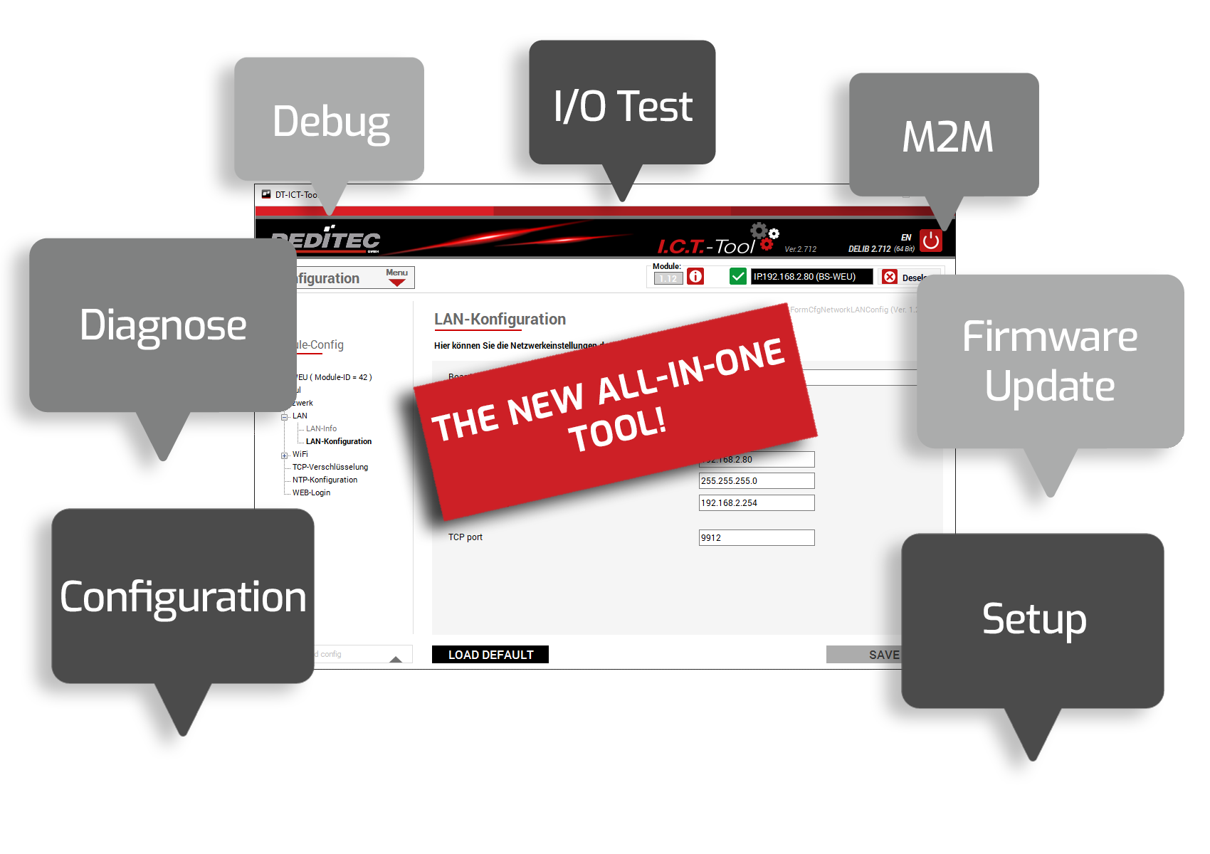
A Windows configuration tool (included) allows users to define a mode in which the module independently captures measurement data (e.g., PWM measurements) from up to two input channels, packs it into a CAN message, and automatically sends this message to a predefined CAN bus address. The time interval for sending can be freely configured.
For example, a CAN message containing two different measurement values (e.g., channel 0 – PWM measurement and channel 1 – distance measurement) can be sent every 10 ms to a specific CAN address automatically by the module.
Similarly, data can also be received automatically by the module. This incoming data is then directly forwarded to the module’s outputs, allowing it to output, for example, a PWM signal.


