Supported third-party software
In addition to conventional control by your own application, our modules can also be operated with ready-made programs or UIs from third-party providers.
The following user interfaces are compatible with our modules:
Control of DEDITEC hardware with Profilab-Expert
Connect DEDITEC products via ProfiLab-Expert!
The ProfiLab-Expert software makes it incredibly easy to develop your own digital or analog measurement projects. Whether analogue measurements, digital controls or a combination of the two - you can use it to implement anything that needs to be electrically controlled. Best of all, you don't need to program a single line! You develop your circuit directly on the PC, add switches, buttons, displays, etc., and build your own project step by step.
The ProfiLab Expert software is a combination of DMM-ProfiLab and Digital-ProfiLab.
It offers all the features of the two individual products plus additional functions, such as the integrated compiler and extensive hardware support.
The new version 4.0 is of course fully backwards compatible with older versions. You can open and continue working on your old projects with the new version without any problems.
The software is very easy to use, so that you can operate it intuitively after a short training period despite its complexity.
The extensive component library contains all the logical and arithmetic components for linking and processing your signals in order to develop your project. In addition to the logical components (such as gates, flip-flops, counters, registers, Rom & Ram, etc.), there are also many metrological components (such as triggers, formula modules, sample & hold elements, comparators, etc.).
Various display options are also available: From a simple LED to an XY recorder, from a pointer instrument to a table, you can use everything to display measured values and statuses on the front panel.
You develop your projects visually like a circuit diagram. Simply drag the required components from the library onto your circuit diagram and wire them accordingly. You can link the individual components together as you wish. There are virtually no limits to your imagination.
Once you have completed your project, you can breathe life into it at the touch of a button.
Your project is simulated in real time. All incoming measured values and signals are processed and displayed immediately, just as you have realized them in your measurement project. The simulation can of course be stopped at any time to make changes to the circuit.
During the simulation, you operate your circuit via a freely configurable front panel. All operating elements such as switches, buttons, but also indicators such as displays, graphs or tables can be present on this front panel. Design the front panel as you wish and label the individual elements. Round off your project professionally with a clear user interface.
The new version works with a large number of hardware (multimeters, cards and external devices) from well-known manufacturers, so there should be something for everyone - from inexpensive to professional. Each piece of hardware appears as a normal component in your circuit. Here you simply connect the desired inputs or outputs. Working with external hardware on your PC has never been so easy. Just press a button and the PC simulates your circuit in real time. Incoming measured values are processed and signals are sent out.
With the integrated compiler, it is possible to convert finished projects into stand-alone applications. These applications created by the ProfiLab software can be started on any Windows PC without the original software having to be installed there. The stand-alone application can no longer be edited once it has been compiled. It may be freely distributed by the owner of the original software. This creates a complete software development system without having to write a single line of program code.
Control of DEDITEC hardware with Licht24 PRO
Control DEDITEC products via Licht24 PRO!
With Licht24 PRO, you can control any devices according to your wishes
quickly and conveniently with your PC. Ideal for discotheques, stages, party rooms,
model railroad control or for use in building services.
A universal control panel or control software for the PC with various features:
- Push-button for momentary operation
- Switch for ON/OFF operation (status LED)
- Emergency stop function
- Blinker with adjustable speed
- Weekly timer with 1 second switching time = max. 86,400 switches/day per channel
- Control switching times via system time or internal stopwatch
- Astro times: sunrise, noon, and sunset times
- Random generator optionally controls 1, 2, 3, or 4 outputs
- 999 programs with up to 99 steps, freely programmable!
- Program or random timing also music-controlled
- Command line parameters
- Pulse mode with adjustable time per channel (e.g. 2000 ms for Eltako or other off-delay)
- Sound output possible when channel is HIGH or LOW
- Counter function available when channel is HIGH
- Custom labeling for each channel
- Informative status display
- Detailed log files of switching operations
- Various skins selectable (12 different interfaces)
- English or German user interface selectable
Special functions:
Weekly timer
The integrated weekly timer offers a multitude of possibilities,
e.g. use the stereo system as an alarm clock, switch on the coffee machine 10 minutes before the alarm time,
as a child safety lock, e.g. switch the TV on at certain times and off again later,
climate control such as switching fans or heaters, controlling water features, in fact
everything that can be done with a timer. Each channel also has a
graphic display of the switching times. The switching times can be controlled via the system time or
the internal stopwatch.
Astro times
By entering the longitude, latitude and time zone, it is possible to calculate the exact sunrise, midday and sunset times for each day. These times can then be used in the timers.
Program mode
The program mode offers up to 999 individual programs, whereby a program consists of
a sequence of up to 99 steps. For example, to program a running light
, channel 1 is set at step 1, channel 2 at step 2, channel 3 at step 3, and so on.
Then set the last step, from which the program starts again from the beginning, and that's it.
Various programs are already stored in positions 1-30.
Random control
1-4 outputs can be controlled randomly via a preset clock. Ideal for
switching several devices on and off alternately at random on a stage or disco.
The last channel can be set, e.g. if the first 8 channels
are to be controlled randomly, the random end value is set to 8.
Music control
The beat can also be controlled via the music. Similar to a
light organ, the bass signal is filtered and a clock pulse is generated. The sound signal is simply connected to the LINE-IN connection of the sound card at
. The light changes in time
with the music, creating a particularly interesting play of light.
Command line parameters
The program can also be controlled with command line parameters.
Licht24 Pro can therefore switch relay cards invisibly in the background.
Example: licht24pro.exe /CONRADSERIAL /1 /1000 switches channel 1 of a Conrad card
on for 1 second, then off again and ends the program.
Sound output
By means of individual sound output for each channel, it is now possible to play any sound at HIGH and/or LOW. By using different sounds, the corresponding channel can be acoustically recognized or accompanied. The 2 standard sounds, which Licht24 Pro contains, play a higher tone at HIGH and a lower tone at LOW (high.wav and low.wav). By using voice files, a function can now also be explicitly announced, e.g. “light on” and “light off” etc. In the model railroad control area, for example, various locomotive sounds or announcements can be played when entering the station.
Counter function
The counter function can be used to count all HIGH switching operations per channel.
Control of DEDITEC hardware with Labview
The process visualization can be used to display entire plant systems on one or more monitors. This makes control and monitoring easy, clear and convenient.
- Petrochemicals, reactor and combustion plants
- Belt conveyor systems, level control systems
Test automation
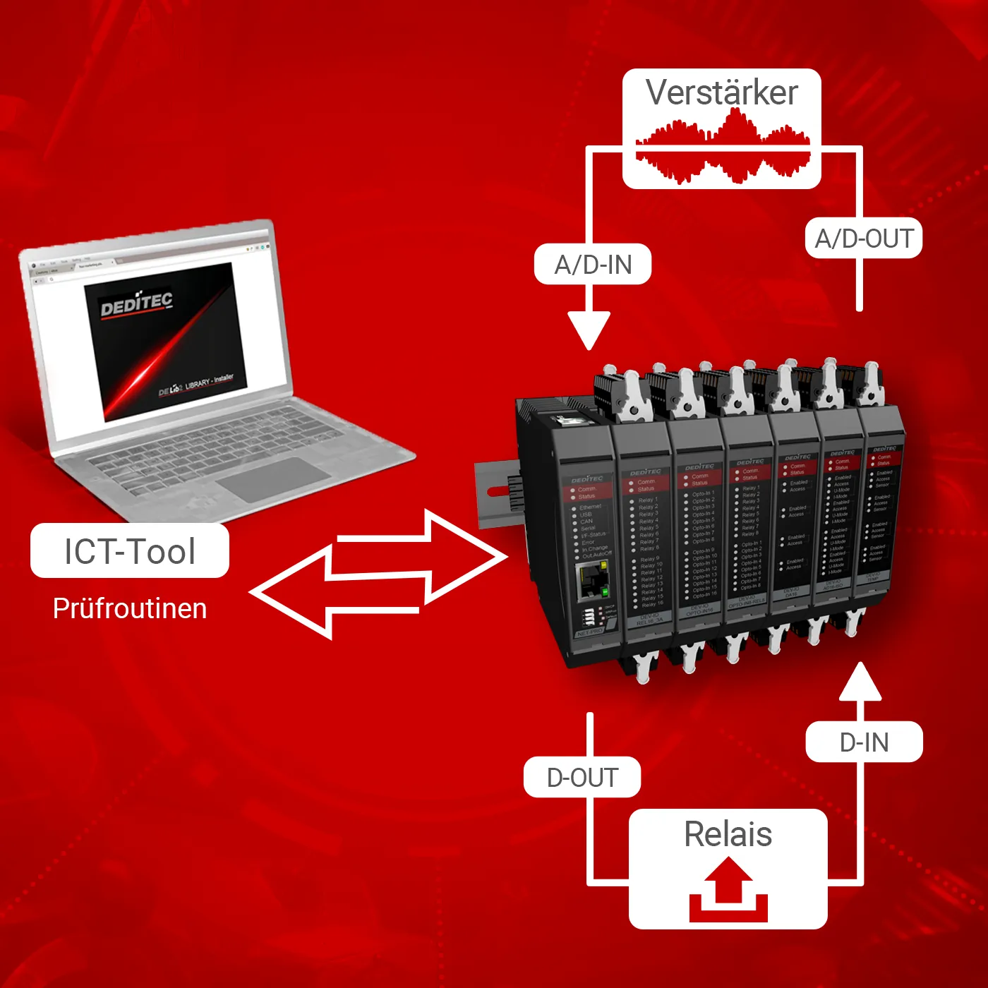
Devices that are to be tested according to a methodical and systematic test procedure can ideally be monitored and carried out fully automatically. For this purpose, we offer to program our modules visually and functionally according to your specifications for LabVIEW. An instantaneous sequence can be displayed with corresponding intermediate steps and final results.
Produced devices that are subject to quality control or product complaints that need to be tested with as little personnel effort as possible can be checked quickly, methodically and easily. Depending on the device, a possible defect can even be narrowed down and displayed. This makes troubleshooting much easier. Deciding whether such a defect should be rectified can be done in the shortest possible time.
- Test tools for controlling device components during individual production steps
- Quality control / final acceptance tests, complaint testing, on-site customer service defect detection using predefined test patterns
Test procedure for quality assurance
As measured values can also be recorded in databases, a complete check of combustion engines in the automotive industry can be carried out in conjunction with our CAN modules, for example. Ideal values (target values), which are pre-stored in the database coupled with tolerance values, can be compared with the actual values of the engine to be tested and reflect the condition by comparing the measured values.
Long-term measurement, data acquisition and evaluation
Optimization tests with the standard settings on combustion engines can also be practically compared by superimposing both measurement curves. Speed, torque, exhaust gas values, consumption, temperature and more can be displayed side by side.
The automated execution of extensive test measurement series is also conceivable in order to determine optimum operating values.
- Weather data logging, climate data recording, visual map display of urban fine dust distribution
- Recording of slow chemical reaction experiments
- Monitoring of cooling systems in the food industry
- Long-term limit value tests of electrical and electronic components (e.g. diffusion measurement of seawater in submarine cables, limit operation of transistors)
Control systems
Systems that need to be automatically adjusted as close as possible to a setpoint value require control.
Bioreactors work optimally in a narrow temperature window due to enzymes. If the temperature is too low, the system does not work efficiently as it works too slowly. If the temperature is too high, a yoghurt, for example, will not achieve the desired consistency. Warning measures are also conceivable.
- Heating and air conditioning systems in large buildings
- Reactors
- Irrigation systems
Virtual instrumentation
LabVIEW is used to visually display measurement systems on standard computers. The advantage of the graphical properties of PCs is utilized to display the systems. Individual combined virtual instrument displays are arranged as required. For example, it is possible to create logically arranged new virtual displays from several measuring devices, making operation considerably simpler and clearer. Virtually operable elements can be added, such as switches, sliders and more. Control loops can also be realized and displayed via displays. Not only an absolute value can be displayed graphically, but also a relative value such as the actual deviation from the setpoint.
