NET-DEV module with 16 relay outputs (3/5A)

ab  318,33

Desined-in-Germany

OUR PROMISE TO YOU:


Our advantages

New feature!

Extended input filter for Digital-IN / Timeout protection function for Digital-Out.
For more information, see the Description and Technical Data tabs!

Availability: In Stock SKU: NET-DEV-REL16_3/5A Category:

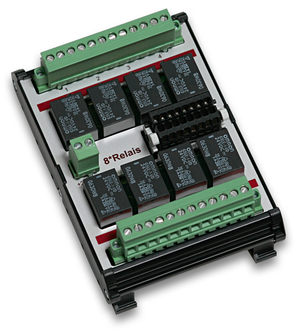
The NET-DEV-REL16_3/5A module has 16 digital outputs and is available with 3A or 5A switching capacity. It serves as an extension possibility for the NET-CPU basic modules and is integrated into an existing NET system by means of Plug’n Play plug connection (DIN Rail-Bus).

  • 16 relay outputs (NO)
  • Max. switching voltage: 48V AC / DC
  • Max. switching current: 5A AC / DC
  • Timer Function
  • Timeout protection

Digital outputs

Relay 3A / 5A

Power relays with normally open (NO) function are used as digital output. They are suitable for switching capacities up to 5A and have a life time of up to 10 million switching cycles. The galvanic separation between input and output circuit is up to 3kV.


Timer Function

All digital outputs of the NET series have a timer function. This allows the outputs to be switched on and off automatically for a freely definable period of time. Even if the connection to the control PC is interrupted.


Fail-safe mode

The fail-safe mode is a safety function in which the DEDITEC module switches to a previously configured, safe switching state in the event of a connection failure.
This is intended to prevent connected installations or systems from continuing to run in an uncontrolled manner.


Three switching states can be defined for each digital output: a) Switched off, b) Switched on or c) Unchanged.


The fail-safe circuit is triggered by a timeout protection function. If the control unit no longer receives any commands from the control PC within a previously defined period of time, the timeout function comes into effect. The cause of a timeout can be a loss of connection between the control PC and the DEDITEC control system or failure of the control PC.


Timeout modes

Three timeout modes are available:


A) “Normal mode” is valid once and must be reactivated manually by software command after each timeout event. The customer application still has access to all controller outputs.


B) In “Auto reactivate mode”, the timeout function is automatically reactivated after communication with the control PC has been re-established. The customer application still has access to all outputs of the control unit.


C) The “Secure outputs mode” blocks access to the outputs after the timeout event. Unlocking can only be carried out by software command. This is an important safety aspect


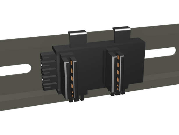
Easy installation thanks to DIN rail bus

Thanks to the practical NET-Bus connector, which is clipped into the top-hat rail, individual modules of a system can be added or exchanged very easily. This Plug’n Play principle makes commissioning easier and eliminates the need for tiresome wiring.


LEDs

On the front side of our NET modules there are a number of status LEDs. These give you a quick overview of the most important functions of the modules, such as the switching states of the individual I/Os, module status or whether clean communication via the DIN rail bus is possible. This can be very helpful for fast error analysis, especially for field applications.


General

Power supply Internal, via the DIN-Rail Bus
Power consumption Max. 130mA/24V
LEDs • Internal bus communication
• Module Status
• One LED per output channel
Timer Function Automatic switching on and off of the outputs within a freely definable time period
Connectors • Typ: Wago Kontakttechnik 713-1108/037-000
• Pluggable 16 pole female connector with locking mechanism
• 100 % malfunction protected
• 1-conductor connection for all types of conductors up to 1.5mm².
DIN Rail-Bus NET bus connector for connection to further NET modules
DIN rail mounting TS 35
Operating temperature +10°C to +50°C
Dimensions 135 mm x 22.5 mm x 111 mm (H x W x D)

Digital outputs

Timeout-Protection-Function • Simple and uncomplicated setting of the timeout protection function possible via software
• Time-definable automatic activation of the timeout protection function in the
Timeout case (between 0.1 seconds and 6553 seconds)
• In the timeout case, digital outputs can be activated, deactivated or left unchanged
• 3 different timeout modes: “normal”, “auto reactive” and “secure outputs” for different procedures in case of a timeout event.
In “secure outputs” timeout mode, access to the outputs is blocked after a timeout event, thus preventing further access to the outputs.
Unlocking must be done by an additional software command.

Relay outputs

Relay up to 3A • 16 outputs
• Type: PCN105D3MHZ
• Property: Normally open contact (NO)
• Max. switching voltage: 48V AC / DC
• Max. switching current: 3A AC / DC
• Max. switching capacity: 90 W
• Galvanic isolation between contact and coil: 3kV RMS /1 min
• Mechanical life: up to 10 million switching cycles
Relay up to 5A • 16 outputs
• Type: PCN105D3MHZ001B
• Property: Normally open contact (NO)
• Max. switching voltage: 48V AC / DC
• Max. switching current: 5A AC / DC
• Max. switching capacity: 150 W
• Galvanic isolation between contact and coil: 3kV RMS /1 min
• Mechanical life: up to 10 million switching cycles


[vrm360 canvas_name=s1 model_url=/wp-content/uploads/2021/01/NET-DEV_REL16-5.obj aspect_ratio=2 initial_offset=1.5 autostart=true lightintensity=0.05 amb_lightintensity=1 button_color=#cc0000 border_width=1 border_color=#acacac backgcolor=#f8f8f8]

Additional information

Weight N/A
Load capacity relay

,


General information on the ICT tool

We have developed the new ICT tool to make commissioning our products as easy and straightforward as possible.
This tool combines all the important functions of our old programs, such as the Configuration Utility, Module Demo and DT-Flasher, in one.
With the ICT tool, you can now easily configure, test, diagnose, flash and debug our products.
In the following chapters, we would like to introduce you to our new all-in-one software in more detail.

Module selection

Here you can integrate your modules into the ICT tool by clicking on the “+” symbol, so that you can then configure or test them.


Start screen

Here you can find some important information about your selected module.
In addition, you can display the manual of the module as PDF or HTML version here.
Under “Show module IDs” you can call up all available module IDs. This ID is needed to integrate our products into your software projects.


ICT Treeview

In the treeview on the left side of the program window, you can see the respective forms that are supported by your module.
With a click you can then display this form in the right part of the program and perform possible configurations or tests.

M2M-CAN

Machine-to-machine, or M2M for short, involves direct communication between two or more modules. Analog or digital data can be sent channel by channel from a source module via the CAN bus to channels of one or more target modules. All products that have a CAN interface are supported. For communication via CAN, the controlled modules only need to be connected to the CAN bus.

M2M-CAN Configuration

In this example, CAN packets are sent every 500ms via the CAN bus to CAN ID 700
These settings can be made in the ICT tool in the CAN-Config area.


For precise and constant reading and writing of measured values at very short intervals, we have developed the software FIFO (“First in-First out”) for our NET series products. With the help of this software, the measured values that are sent from the PC to the NET module, for example, are temporarily stored in a FIFO buffer. These are then processed independently by the module at a defined time interval.

To put it simply: measured values are collected and stored in the buffer for both “FIFO In” and “FIFO Out” and then passed on in packets. This eliminates delays caused by traffic, spatial distances or other disruptive factors and significantly improves measurement processes.


All the advantages at a glance:

  • Analog and digital values can be read out at very short intervals (milliseconds)
  • Exact reading of the values in a self-defined time interval possible
  • With higher utilization via the Ethernet interface, the FIFO does not consume more traffic


Testing and programming

With our ICT tool, you can test and diagnose the FIFO-IN and FIFO-OUT with digital and analog I/Os.
You will also find help for correct programming in the source code of our FIFO sample programs.


General Handling

DapiOpenModule
This function opens a particular module.

DapiOpenModule


Description

This function opens a specific module


Definition

ULONG DapiOpenModule(ULONG moduleID, ULONG nr);


Parameters

moduleID=Specifies the module to be opened (see delib.h)
nr=Specifies which one (in case of several modules) should be opened.
nr=0 -> 1st module
nr=1 -> 2nd module


Return-Value

handle=Corresponding handle for the module
handle=0 -> module was not found


Comment

The handle returned by this function is needed to identify the module for all other functions.


Programming example

// Open USB module
handle = DapiOpenModule(RO_USB1, 0);
printf(“handle = %x\n”, handle);
if (handle==0)
{
// USB module was not found
printf(“Modul konnte nicht geöffnet werden\n”);
return;
}

DapiCloseModule
This command closes an opened module.

DapiCloseModule


Description

This command closes an open module.


Definition

ULONG DapiCloseModule(ULONG handle);


Parameters

handle=This is the handle of an open module


Return-Value

None


Programming example

// Close module
DapiCloseModule(handle);

DapiGetLastError
This function returns the last registered error. If an error has occurred, it must be deleted with DapiClearLastError(), otherwise any call of DapiGetLastError() will return the "old" error. If multiple modules are used, the use of DapiGetLastErrorByHandle() is recommended.

DapiGetLastError


Description

This function returns the last detected error. If an error occurred, it must be cleared with DapiClearLastError(), otherwise any call to DapiGetLastError() will return the “old” error.
If more than one module should be used, it is recommended to use DapiGetLastLastErrorByHandle().


Definition

ULONG DapiGetLastError(void);


Parameters

None


Return-Value

Error Code
0=no error. (see delib_error_codes.h)


Programming example

BOOL IsError()
{
unsigned char msg[500];
unsigned long error_code = DapiGetLastError();

if (error_code != DAPI_ERR_NONE)
{
DapiGetLastErrorText((unsigned char*) msg, sizeof(msg));
printf(“Error Code = 0x%x * Message = %s\n”, error_code, msg);

DapiClearLastError();

return TRUE;
}

return FALSE;
}

DapiGetLastErrorByHandle
This function returns the last registered error of a particular module (handle). If an error has occurred, it must be deleted with DapiClearLastErrorByHandle(), otherwise any call of DapiGetLastErrorByHandle() will return the "old" error.

DapiGetLastErrorByHandle


Description

This function returns the last detected error of a specific module (handle). If an error occurred, it must be cleared with DapiClearLastErrorByHandle(), otherwise any call to DapiGetLastErrorByHandle() will return the “old” error.


Definition

ULONG DapiGetLastErrorByHandle(ULONG handle);


Parameters

handle=This is the handle of an open module


Return-Value

Error Code
0=no error. (see delib_error_codes.h)


Programming example

BOOL IsError(ULONG handle)
{
unsigned long error_code = DapiGetLastErrorByHandle(handle);

if (error_code != DAPI_ERR_NONE)
{
printf(“Error detected on handle 0x%x – Error Code = 0x%x\n”, handle, error_code);

DapiClearLastErrorByHandle(handle);

return TRUE;
}

return FALSE;
}

DapiGetLastErrorText
This function reads the text of the last registered error. If an error has occurred, it must be cleared with DapiClearLastError(), otherwise every call of DapiGetLastErrorText() returns the "old" error. Definition

DapiGetLastErrorText


Description

This function reads the text of the last detected error. If an error occurred, it must be cleared with DapiClearLastError(), otherwise any call to DapiGetLastErrorText() will return the “old” error.


Definition

ULONG DapiGetLastErrorText(unsigned char * msg, unsigned long msg_length);


Parameters

msg = Buffer for the text to be received
msg_length = Length of the text buffer


Programming example

BOOL IsError()
{
unsigned char msg[500];
unsigned long error_code = DapiGetLastError();

if (error_code != DAPI_ERR_NONE)
{
DapiGetLastErrorText((unsigned char*) msg, sizeof(msg));
printf(“Error Code = 0x%x * Message = %s\n”, error_code, msg);

DapiClearLastError();

return TRUE;
}

return FALSE;
}

DapiClearLastError
This function deletes the last error registered with DapiGetLastError().

DapiClearLastError

Description

This function deletes the last error registered with DapiGetLastError().


Definition

void DapiGetLastError(void);


Parameters

None


Return value

None


Example program

BOOL IsError()
{
unsigned char msg[500];
unsigned long error_code = DapiGetLastError();

if (error_code != DAPI_ERR_NONE)
{
DapiGetLastErrorText((unsigned char*) msg, sizeof(msg));
printf(“Error Code = 0x%x * Message = %s\n”, error_code, msg);

DapiClearLastError();

return TRUE;
}

return FALSE;
}

DapiClearLastErrorByHandle
This function deletes the last error of a particular module (handle), which was registered with DapiGetLastErrorByHandle().

DapiClearLastErrorByHandle


Description

This function deletes the last error of a particular module (handle), which was registered with DapiGetLastErrorByHandle().


Definition

void DapiClearLastErrorByHandle(ULONG handle);


Parameters

handle=This is the handle of an opened module.


Return value

None


Example program

BOOL IsError(ULONG handle)
{
unsigned long error_code = DapiGetLastErrorByHandle(handle);

if (error_code != DAPI_ERR_NONE)
{
printf(“Error detected on handle 0x%x – Error Code = 0x%x\n”, handle, error_code);

DapiClearLastErrorByHandle(handle);

return TRUE;
}

return FALSE;
}

DapiGetDELIBVersion
This function returns the installed DELIB version.

DapiGetDELIBVersion


Description

This function returns the installed DELIB version.


Definition

ULONG DapiGetDELIBVersion(ULONG mode, ULONG par);


Parameters

mode=Mode with which the version is read (must always be 0).
par=This parameter is not defined (must always be 0).


Return-Value

version=Version number of the installed DELIB version [hex]


Programming example

version = DapiGetDELIBVersion(0, 0);
//With installed version 1.32 version = 132(hex)

DapiOpenModuleEx
This function opens a specific module with ethernet interface.The particularity of this command is,that parameters like IP-address, portnumber and the duration of the timeout can be specified. The opening of the module is independent of the DELIB Configuration Utility settings.

DapiOpenModuleEx


Description

This function specifically opens a module with an Ethernet interface. The parameters IP address, port number and the duration of the timeout can be determined.


Definition

ULONG DapiOpenModuleEx(ULONG moduleID, ULONG nr, unsigned char* exbuffer, 0);


Parameters

moduleID = Specifies the module to be opened (see delib.h)
nr = Specifies which one (in case of several modules) is to be opened
nr = 0 -> 1st module
nr = 1 -> 2nd module
exbuffer = buffer for IP address, port number and duration of the timeout


Return-Value

handle = Corresponding handle for the module
handle = 0 -> module was not found


Comment

The handle returned by this function is required to identify the module for all other functions.
This command is supported by all modules with Ethernet interface.


Programming example

// Open ETH-Module with parameter

DAPI_OPENMODULEEX_STRUCT open_buffer;

strcpy((char*) open_buffer.address, “192.168.1.10”);
open_buffer.portno = 0;
open_buffer.timeout = 5000;

handle = DapiOpenModuleEx(RO_ETH, 0, (unsigned char*) &open_buffer, 0);
printf(“Module handle = %x\n”, handle);

Digital output functions

DapiDOSet1
This is the command to set a single output.

DapiDOSet1


Description

This command sets a single output.


Definition

void DapiDOSet1(ULONG handle, ULONG ch, ULONG data);


Parameters

handle=This is the handle of an open module
ch= Specifies the number of the output to be set (0 .. )
data= Specifies the data value to be written (0 / 1)


Return-Value

None


Requirements

The following SW feature bits must be supported by the module:


DAPI_SW_FEATURE_BIT_CFG_DO

The following conditions for the transfer parameters must be met:

maxCh = DapiSpecialCommand(handle, DAPI_SPECIAL_CMD_GET_MODULE_CONFIG, DAPI_SPECIAL_GET_MODULE_CONFIG_PAR_DO, 0, 0)
maxCh > ch

DapiDOSet8
This command sets 8 digital outputs simultaneously.

DapiDOSet8


Description

This command sets 8 digital outputs simultaneously.


Definition

void DapiDOSet8(ULONG handle, ULONG ch, ULONG data);


Parameters

handle=This is the handle of an open module
ch= Specifies the number of the output from which writing is to start (0, 8, 16, 24, 32, ..)
data=Specifies the data values to be written


Return-Value

None

DapiDOSet16
This command sets 16 digital outputs simultaneously.

DapiDOSet16


Description

This command sets 16 digital outputs simultaneously.


Definition

void DapiDOSet16(ULONG handle, ULONG ch, ULONG data);


Parameters

handle=This is the handle of an open module
ch= Specifies the number of the output from which writing is to start (0, 16, 32, ..)
data=Specifies the data values to be written


Return-Value

None

DapiDOSet32
This command sets 32 digital outputs simultaneously.

DapiDOSet32


Description

This command sets 32 digital outputs simultaneously.


Definition

void DapiDOSet32(ULONG handle, ULONG ch, ULONG data);


Parameters

handle=This is the handle of an open module
ch= Specifies the number of the output from which writing is to start (0, 32, 64, ..)
data=Specifies the data values to be written


Return-Value

None


Programming example

// Write a value to the outputs
data = 0x0000ff00; // outputs 9-16 are set to 1
DapiDOSet32(handle, 0, data); // Chan Start = 0
printf(“Write to outputs data=0x%x\n”, data);
printf(“key for further\n”);
getch();
// —————————————————-
// Write a value to the outputs
data = 0x80000000; // Output 32 is set to 1
DapiDOSet32(handle, 0, data); // Chan Start = 0
printf(“Write to outputs data=0x%x\n”, data);
printf(“key for further\n”);
getch();
// —————————————————-
// Write a value to the outputs
data = 0x80000000; // Output 64 is set to 1
DapiDOSet32(handle, 32, data); // Chan Start = 32
printf(“Write to outputs data=0x%x\n”, data);
printf(“key for further\n”);
getch();

DapiDOSet64
This command is to set 64 digital outputs.

DapiDOSet64


Description

This command sets 64 digital outputs simultaneously.


Definition

void DapiDOSet64(ULONG handle, ULONG ch, ULONGLONG data);


Parameters

handle=This is the handle of an open module
ch= Specifies the number of the output from which writing is to start (0, 64, ..)
data=Specifies the data values to be written


Return-Value

None

DapiDOClrBit32
With this command you can change the states of outputs to 0 without changing the states of the neighboring outputs.

DapiDOClrBit32


Description

This command can be used to switch outputs selectively to 0 without changing the states of adjacent outputs.


Definition

void DapiDOClrBit32(uint handle, uint ch, uint data);


Parameters

handle = This is the handle of an open module
ch = Specifies the number of the output from which writing is to start
data = Specifies the data value to be written (up to 32 bits)


Return-Value

None


Comment

Only the bits with a value of 1 in the data parameter are considered by the command.


Programming example

data = 0x1; // Output 0 would be changed to 0. The states of outputs 1-31 won’t be changed
DapiDOSetBit32(handle, 0, data);

data = 0xf; // Outputs 0-3 would be changed to 0. The states of outputs 4-31 won’t be changed
DapiDOSetBit32(handle, 0, data);

data = 0xff; // Outputs 0-7 would be changed to 0. The states of outputs 8-31 won’t be changed
DapiDOSetBit32(handle, 0, data);

data = 0xff000000; // Outputs 23-31 would be changed to 0. The states of outputs 0-21 won’t be changed
DapiDOSetBit32(handle, 0, data);

DapiDOSet1_WithTimer
This function sets a digital output (ch) to a value (data - 0 or 1) for a specified time in msec.

DapiDOSet1_WithTimer


Description

This function sets a digital output (ch) to a value (data – 0 or 1) for a certain time in ms.


Definition

void DapiDOSet1_WithTimer(ULONG handle, ULONG ch, ULONG data, ULONG time_ms);


Parameters

handle=This is the handle of an open module
ch= Specifies the number of the output to be set (0 .. )
data= Specifies the data value to be written (0 / 1)
time_ms=Specifies the time in which the output is set [ms].


Return-Value

None


Comment

This command is supported by all output modules of the NET series as well as by our RO-O8-R8 module.
This command loses its validity if it is overwritten with other values.
If you want to deactivate the command, it must be overwritten with time_ms=0.


Programming example

DapiDOSet1_WithTimer(handle, 2, 1, 1000);
//Setting channel 2 for 1000msec to 1

DapiDOSetBit32
With this command you can change the states of outputs to 1 without changing the states of the neighboring outputs.

DapiDOSetBit32


Description

This command can be used to switch outputs selectively to 1 without changing the states of adjacent outputs.


Definition

void DapiDOSetBit32(uint handle, uint ch, uint data);


Parameters

handle = This is the handle of an open module
ch = Specifies the number of the output from which writing is to start
data = Specifies the data value to be written (up to 32 bits)


Return-Value

None


Comment

Only the bits with a value of 1 in the data parameter are considered by the command.


Programming example

data = 0x1; // Output 0 would be changed to 1. The states of outputs 1-31 won’t be changed
DapiDOSetBit32(handle, 0, data);

data = 0xf; // Outputs 0-3 would be changed to 1. The states of outputs 4-31 won’t be changed
DapiDOSetBit32(handle, 0, data);

data = 0xff; // Outputs 0-7 would be changed to 1. The states of outputs 8-31 won’t be changed
DapiDOSetBit32(handle, 0, data);

data = 0xff000000; // Outputs 23-31 would be changed to 1. The states of outputs 0-21 won’t be changed
DapiDOSetBit32(handle, 0, data);

DapiDOReadback32
This command reads back the 32 digital outputs.

DapiDOReadback32


Description

This command reads back the 32 digital outputs.


Definition

ULONG DapiDOReadback32(ULONG handle, ULONG ch);


Parameters

handle=This is the handle of an open module
ch= Specifies the number of the output from which the read back is to be performed (0, 32, 64, ..)


Return-Value

Status of 32 outputs.

DapiDOReadback64
This command reads the current PWM frequency of the module

DapiDOReadback32


Description

This command reads back the 32 digital outputs.


Definition

ULONG DapiDOReadback32(ULONG handle, ULONG ch);


Parameters

handle=This is the handle of an open module
ch= Specifies the number of the output from which the read back is to be performed (0, 32, 64, ..)


Return-Value

Status of 32 outputs.

Web Interface – Interface

All DEDITEC Ethernet modules have a web interface that allows you to make settings conveniently via your web browser and also gives you direct access to the I/Os.

This allows you to access the product with a smartphone, tablet or even a PC via a browser.

The following I/O units are supported:


  • Digital inputs
  • Digital inputs (counter function)
  • Digital outputs
  • Analog inputs (voltage & current)
  • Analogue outputs (voltage & current)
  • PT100 temperature detection
  • Stepper motor control

You can protect the Ethernet module against unauthorized access with a user system and optional encryption system.

General

Start page of the web interface. The navigation on the left side gives you access to various setting options.

Network configuration

All network settings can be made directly via the web interface.

Usermanager

Here you can define the user name and password for access to the web interface. If the user is inactive, he/she is automatically logged out after the session time has expired.

Status / Reboot

Version of the installed firmware. Functions for restarting and resetting the settings.

Security

In addition to a user/password system for the web interface, we also offer you the option of encrypting the entire network communication. Access to the I/Os can also be blocked.

Supported I/Os

In the following we show you the supported I/Os that you can operate via the web interface.

Digital Inputs

The picture shows the overview of the digital inputs. You can switch between several inputs via the drop-down menu. The column ‘State’ shows whether a signal is present at the input.

Digital Inputs Counter

Our digital inputs have a counting function. The counter reading can be read and reset via the web interface.

Digital Outputs

The digital outputs can be switched via an on/off button. The current status of the outputs can be read back via the ‘Readback’ column.

Analogue Inputs

Current and voltage can also be read out via the web interface. The desired operating mode can be set via the A/D Mode drop-down menu.

Analogue Outputs

Analogue signals can also be output via the web interface. The desired D/A mode can be set via the drop-down menu, as with the analog inputs. The desired value can be written to the outputs using the ‘SET’ button. The column ‘Readback’ shows the current voltage/current output of the D/A converter.

Temperature measurement (PT100)

The temperature measurement is supported by our RO series.


PT100

The current temperature can be read. If no sensor is connected to the channel, this is signalled with ‘disconnected’.

Stepper-Motor Control

The position and speed of the stepper motor can be set via the control elements. The status window shows the current position, temperature and power supply.

I/O Control APP for Android™


Get it on Google Play


Control the digital and analog I/Os of our Ethernet modules from on the road. With the DEDITEC I/O control Android App, any network-compatible Android device can be remotely controlled for DEDITEC products with Ethernet interface


Features:

  • Separate storage of network settings for private and public networks
  • Better clarity through configurable I/O names
  • Configurable refresh of all I/Os

The following I/Os are supported:

  • up to 128 analog inputs (0..10V, 0..5V, +/- 10V and +/- 5V)
  • up to 64 analog outputs (0..10V, 0..5V, +/- 10V and +/- 5V)
  • up to 128 digital inputs and outputs

Network settings
A configuration for private (WLAN) or public (Internet) networks can be created and saved in the network settings.


Module configuration

At the module configuration you see the number of connected I/O modules.

You can also select here which I/Os are to be controlled.


Digital inputs
The digital inputs are scanned at an adjustable interval.


Digital outputs
In the area of the digital outputs the channels can be switched on or off individually.

It is also possible to switch all channels on or off.


Analogue inputs
For the analog inputs you can select from the measuring ranges 0..10V, 0..5V, +/- 10V or +/- 5V.

The A/D channels are scanned automatically at an adjustable interval.


Analogue outputs
Here you may set analog outputs in the measuring range 0..10V, 0..5V, +/- 10V or +/- 5V.


Settings
This picture shows the settings for analog outputs. Each channel can be given a name here.

It can also be defined here whether and at what interval the analog outputs are read back.

These settings are available for all I/Os.


Block diagram NET-DEV-REL16

Block diagram NET-DEV-REL16

Connection example Relay

Connection example

Screwless connector system

The customer’s connection wiring of the inputs and outputs is carried out via screwless, pluggable terminal strips. The conductor connection is made by a so-called actuating tool.
A locking and ejection mechanism facilitates the insertion and removal of the complete terminal strip.


Handling

Step 1

Remove the operating tool from the scope of delivery.

Step 2

Insert the operating tool firmly into the side opening in the direction of conductor connection.

Step 3

Now insert the stripped conductor into the open terminal contact.

Schritt 4

Pull the operating tool out again.

Step 5

Check the correct connection of the conductor. It should now no longer be possible to pull it out easily.

Manual

Manual NET-Serie
Hard- und Software description
Download
  • Description NET-CPU Modules
  • Description NET-DEV Digital Modules


DELIB driver library

Manual of the DELIB driver library
Documentation of all functions for the driver library
Download
  • Windows 10, 8, Vista, 7, XP, 2000 andLinux
  • Moduel open/close functions
  • Digital inputs: reading 1 / 8 / 16 / 32 / 64 bit
  • Digital outputs: Write 1 / 8 / 16 / 32 / 64 bit
  • A/D Lesen: read, read_volt, read_mA, A/D Modus einstellen
  • D/A schreiben: write, write_volt, write_mA, D/A-Modus einstellen
DELIB (64-bit) driver library for Windows
For Windows 11/10, Windows 7, Windows 8, Vista, XP and 2000
Download

Installation file for the 64 bit DELIB driver library.

The following operating systems are supported:

64 bit

  • Windows 11/10 x64
  • Windows 7 x64
  • Windows 8 x64
  • Windows Server 2012 x64
  • Windows Server 2008 x64
  • Windows Vista x64
  • Windows XP x64
  • Windows Server 2003 x64

Included software

  • DT-Flasher x64
    Software to update DEDITEC module to the latest version
  • DELIB Configuration Utility x64
    Set configuration of module addresses
  • DELIB Module Config x64
    Configuration of module-specific settings
  • CAN Configuration Utility x64
    Set configuration of CAN modules
  • DELIB Module Demo x64
    Enables manual switching of a module
  • DELIB Command Line Interface x64
    Enables the execution of DELIB commands in the command line
  • Watchdog Configuration Utility x64
    Set configuration of a watchdog stick
DELIB (32-bit) driver library for Windows
For Windows 11/10, Windows 7, Windows 8, Vista, XP and 2000
Download

Installation file for the 32-bit version of the DELIB driver library.

The following operating systems are compatible:
32-Bit

    • Windows 11/10
    • Windows 7
    • Windows 8
    • Windows Server 2012
    • Windows Server 2008
    • Windows Vista
    • Windows XP
    • Windows Server 2003

64-Bit

  • Windows 10 x64
  • Windows 7 x64
  • Windows 8 x64
  • Windows Server 2012 x64
  • Windows Server 2008 x64
  • Windows Vista x64
  • Windows XP x64
  • Windows Server 2003 x64

Included software

  • DT-Flasher
    Software to update DEDITEC module to the latest version
  • DELIB Configuration Utility
    Set configuration of module addresses
  • DELIB Module Config
    Configuration of module-specific settings
  • CAN Configuration Utility
    Set configuration of CAN modules
  • DELIB Module Demo
    Enables manual switching of a module
  • DELIB Command Line Interface
    Enables the execution of DELIB commands in the command line
  • Watchdog Configuration Utility
    Set configuration of a watchdog stick

Attention:

With this version of the driver library, only 32-bit applications can be created, which can then be run on 32- and 64-bit systems.

DELIB driver library for Linux (32/64-bit)
For 32/64-bit Linux distributions starting with kernel 2.6.x
Download

DELIB driver library for Linux distributions (32/64-bit) starting with kernel 2.6.x

This driver package includes the following components:

  • DELIB USB driver
  • DELIB Ethernet driver
  • DELIB CLI

DELIB USB driver

Supports the following products:

  • NET-Series (via USB interface)
  • RO-USB-Series
  • BS-USB-Series
  • USB-Mini-Sticks
  • USB-Watchdog
  • USB-OPTION-8 / USB-RELAIS-8
  • USB-TTL-32 / USB-TTL-64

Note:

With the standard USB driver, you can access several USB products with different module IDs (for example one RO-USB and one USB-OPTOIN-8). Therefore, no additional driver installation is required.

If you want to access several USB products with the same module ID (for example one USB-OPTOIN-8 and one USB-RELAIS-8), you have to install additionally the Linux FTDI driver. The FTDI driver can be found at http://www.ftdichip.com.


DELIB Ethernet driver

Supports the following products:

  • NET-Series (via Ethernet Interface)
  • RO-ETH-Series
  • RO-ETH/LC-Series
  • BS-ETH-Serie
  • ETH-OPTION-8 / ETH-RELAIS-8
  • ETH-TTL-64

DELIB CLI

With the DELIB CLI (Command Line Interface) for Linux it is possible so controll all I/O’s over the command-line.


DELIB - Sample-Sources - Installer (approx. 10 MB)
Sample programs for different programming languages (Also in DELIB Setup included)
Download

Sample programs for different programming languages (Also in DELIB Setup included)

  • C (Microsoft Visual C++ 6.0, Borland C)
  • C++ (Microsoft Visual C++ 6.0)
  • C# (Microsoft Visual C# 2008 to 2015)
  • Delphi (Borland Delphi 7)
  • VB (Microsoft Visual Basic 6.0)
  • VB.NET (Microsoft Visual Basic 2008 to 2015)
  • Java (Java native interface)
  • Java.dll (Ethernet protocol for ethernet products)


16 pol connector

Required to connect your application to the DEDITEC module

  • Type: Wago Kontakttechnik 713-1108/037-000
  • Pluggable female connector with locking mechanism
  • 100 % malfunction protected
  • 1-wire connection for all types of conductors up to 1.5mm²

Tool for wiring connectors

Serves to open and close the clamp contacts on the Wago connectors.
  • Type: Wago Kontakttechnik 734-231

DIN rail connector

The DIN-Rail connector is a single BUS segment which allows the connection to other modules. It is clipped into the DIN-rail and plugged into the side of an existing DIN-Rail connector.

  • DIN-Rail Bus Connectors
  • Connection of a NET or COS module
  • For extension of the NET or COS bus system
  • 1 piece

8-times relay powermodule (switching capacity 40V/10A), which can be controlled by relays/opto-couplers

The MOD-REL8_10A has eight changeover relays with a switching capacity of 48V/10A AC or 30V/8A DC. It can be used as additional power stage for our digital output modules. The normally open contacts of a digital output module, e.g. a RO-USB-REL16, are simply connected in parallel to the inputs of this power stage. Additionally this module requires a power supply of 24V DC.

  • Power stage for all digital output modules
  • 8 change-over contact relay (CO) / 48V / 10A AC or. 30V / 8A DC
  • 24V power supply
  • Pluggable terminal strips for the connection wiring
  • Potential-free inputs (no control voltage required)

Power supply 24V/2A for DIN rail mounting

The DR-4524 from Mean Well is a 48W rail mount power supply for industrial applications. It offers protection against short circuit, overload, overvoltage and overheating.

  • Input voltage range: 85V… 264V AC / 120V DC … 370V DC
  • Output voltage: 24V DC
  • Output current: 2A
  • Nominal power: 48W

12V din rail relay

PLC interface for limiting continuous currents up to 10A, consisting of basic terminal with screw connection and pluggable miniature relay. Mountable on NS 35/7.5 mounting rail.

  • Nominal voltage: 230V AC / 220V DC
  • Switching voltage: 250 V AC/DC
  • 1 changeover contact
  • Reverse polarity protection, freewheeling diode
  • LED for voltage indication
  • Phoenix Contact, 2967617, PLC-RSC- 12DC/21HC

24V din rail relay

PLC interface for limiting continuous currents up to 10A, consisting of basic terminal with screw connection and pluggable miniature relay. Mountable on NS 35/7.5 DIN rail.

  • Nominal voltage: 24V AC/DC
  • Switching voltage: 250 V AC/DC
  • 1 changeover contact
  • Reverse polarity protection, freewheeling diode
  • LED for voltage indication
  • Phoenix Contact, 2967633, PLC-RSC- 24UC/21HC

DIN rail connector

The DIN-Rail connector is a single BUS segment which allows the connection to other modules. It is clipped into the DIN-rail and plugged into the side of an existing DIN-Rail connector.

  • DIN-Rail Bus Connectors
  • Connection of a NET or COS module
  • For extension of the NET or COS bus system
  • 1 piece

16 pol connector

Required to connect your application to the DEDITEC module

  • Type: Wago Kontakttechnik 713-1108/037-000
  • Pluggable female connector with locking mechanism
  • 100 % malfunction protected
  • 1-wire connection for all types of conductors up to 1.5mm²

Strain relief plate for 16 or 18 pole Wago connectors

A strain relief plate that can be mounted centrally between the conductor entries facilitates the plugging and unplugging process and allows easy access to the actuation openings even when wired.

  • Type: Wago / 713-127
  • Suitable for 16/18 pole female connectors with conductor connection
  • Mating and unmating aid for Wago connectors
  • Strain relief of the individual wired conductors
  • Easy mounting

Tool for wiring connectors

Serves to open and close the clamp contacts on the Wago connectors.
  • Type: Wago Kontakttechnik 734-231

DIN Rail

Top-hat rail for mounting our control technology modules.

  • Top-hat rail according to DIN EN 50022
  • Type: Phoenix Contact / 1208131
  • Dimensions in mm: 450 x 35 x 7.5 (L x W x D)