


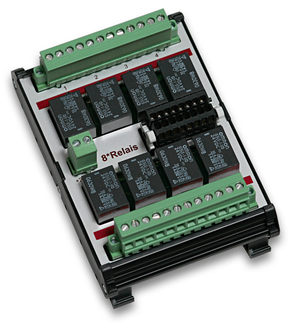
The USB-Relay-8 is a compact USB 2.0 module in a plastic housing with 8 relay outputs for low switching capacities up to max. 1 A. A number of status LEDs visualize the switching states of the relays. The connection wiring is done via two 8 pole pluggable screw terminals.
- 8 *Relay outputs NO (36V DC / 1A / 10 W)
- Galvanic isolation between contact and coil: 1.5 kV RMS /1 min
- Timeout protection function
- LED status display per output channel

Relay outputs
Reed relays with normally open (NO) function are used in this product. They are suitable for smaller switching capacities and achieve well over 100 million switching cycles. The electrical isolation between input and output circuit is up to 1.5kV.

Fail-safe mode
The fail-safe mode is a safety function in which the DEDITEC module switches to a previously configured, safe switching state in the event of a connection failure.
This is intended to prevent connected installations or systems from continuing to run in an uncontrolled manner.
Three switching states can be defined for each digital output: a) Switched off, b) Switched on or c) Unchanged.
The fail-safe circuit is triggered by a timeout protection function. If the control unit no longer receives any commands from the control PC within a previously defined period of time, the timeout function comes into effect. The cause of a timeout can be a loss of connection between the control PC and the DEDITEC control system or failure of the control PC.
Timeout modes
Three timeout modes are available:
A) “Normal mode” is valid once and must be reactivated manually by software command after each timeout event. The customer application still has access to all controller outputs.
B) In “Auto reactivate mode”, the timeout function is automatically reactivated after communication with the control PC has been re-established. The customer application still has access to all outputs of the control unit.
C) The “Secure outputs mode” blocks access to the outputs after the timeout event. Unlocking can only be carried out by software command. This is an important safety aspect

LEDs
Each digital input and output has a separate LED that lights up when the signal state is active. Furthermore, the status of the operating voltage, the communication with the interface, error events or the occurrence of a timeout can be displayed.

Connectors
Pluggable screw terminals are used as connectors. Conductor cross-sections of up to 3.3mm² can be connected. The two flange screw connections provide additional support.


Reviews
There are no reviews yet.