


The RO-(ETH/LC)/(USB)-O16-64-M16-64 module is available in versions with 16, 32 or 64 inputs and outputs. For the digital inputs AC optocouplers are used, while P-Ch. MOSFETs were used for the digital outputs. As interface option you can choose between an Open Source Ethernet connection with galvanic isolation or a standard USB 2.0 connection.
- Ethernet interface 10/100 Mbit with galvanic isolation
- Web interface
- Open Ethernet Protocol
- USB 2.0 interface up to 480 Mbit
- 16/32/64 Digital inputs: 15V – 30V AC/DC (optional 5V – 15V)
- 16/32/64 MOSFET outputs: 2A
- 16 bit counter per channel (up to 100Hz)
- LED status display per input and output channel
- Timeout protection function

Digital inputs
With our optocoupler inputs, digital signal states can be recorded within a voltage range of 5V to 30V AC or DC. Input and output circuits are galvanically isolated from each other up to 2.5kV.
Digital In Input Filter
With our Digital-In modules, an input filter can be set in a time interval of 1ms…255ms to filter interference pulses.
This means that AC signals can also be detected cleanly.
Counter
Each input has a 16 bit counter that can count up to 65535 pulses. If the maximum counter value is exceeded, the counting process starts again from zero. By means of a software command, the current status of all input counters can be read from the module simultaneously.
Recording of status changes
Status changes that occur between the readout cycles are reliably detected by internal flip-flops and can be read out separately by software. In addition, such an event is signalled by a status LED. Resetting is done automatically after the flip-flops have been read out.

MOSFET 2A
With the option “Optocoupler outputs (2A)” P-Ch MOSFETs are used. They are suitable for switching capacities up to 2A DC and are practically wear-free.

Fail-safe mode
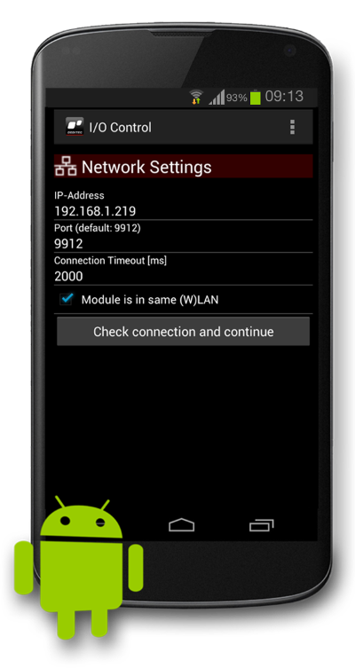
The fail-safe mode is a safety function in which the DEDITEC module switches to a previously configured, safe switching state in the event of a connection failure.
This is intended to prevent connected installations or systems from continuing to run in an uncontrolled manner.
Three switching states can be defined for each digital output: a) Switched off, b) Switched on or c) Unchanged.
The fail-safe circuit is triggered by a timeout protection function. If the control unit no longer receives any commands from the control PC within a previously defined period of time, the timeout function comes into effect. The cause of a timeout can be a loss of connection between the control PC and the DEDITEC control system or failure of the control PC.
Timeout modes
Three timeout modes are available:
A) “Normal mode” is valid once and must be reactivated manually by software command after each timeout event. The customer application still has access to all controller outputs.
B) In “Auto reactivate mode”, the timeout function is automatically reactivated after communication with the control PC has been re-established. The customer application still has access to all outputs of the control unit.
C) The “Secure outputs mode” blocks access to the outputs after the timeout event. Unlocking can only be carried out by software command. This is an important safety aspect

LEDs
Each digital input and output has a separate LED that lights up when the signal state is active. Furthermore, the status of the operating voltage, the communication with the interface, error events or the occurrence of a timeout can be displayed.

Connectors
A screwless system from the manufacturer WAGO Kontakttechnik is used as the connector. The 1-wire female connectors are 100% protected against mismating and have an eject and locking mechanism. All conductor types up to 1.5mm² can be connected.


Reviews
There are no reviews yet.